Here are the types of hydro turbines!
There are two main types of hydro turbines: impulse and reaction. The type of hydropower turbine selected for a project is based on the height of standing water—referred to as "head"—and the flow, or volume of water, at the site. Other deciding factors include how deep the turbine must be set, efficiency, and cost.
Impulse Turbine The impulse turbine generally uses the velocity of the water to move the runner and discharges to atmospheric pressure. The water stream hits each bucket on the runner. There is no suction on the down side of the turbine, and the water flows out the bottom of the turbine housing after hitting the runner. An impulse turbine is generally suitable for high head, low flow applications.
Pelton A pelton wheel has one or more free jets discharging water into an aerated space and impinging on the buckets of a runner. Draft tubes are not required for impulse turbine since the runner must be located above the maximum tailwater to permit operation at atmospheric pressure. A Turgo Wheel is a variation on the Pelton and is made exclusively by Gilkes in England. The Turgo runner is a cast wheel whose shape generally resembles a fan blade that is closed on the outer edges. The water stream is applied on one side, goes across the blades and exits on the other side.
A pelton turbine.
- Cross-Flow
A cross-flow turbine is drum-shaped and uses an elongated, rectangular-section nozzle directed against curved vanes on a cylindrically shaped runner. It resembles a "squirrel cage" blower. The cross-flow turbine allows the water to flow through the blades twice. The first pass is when the water flows from the outside of the blades to the inside; the second pass is from the inside back out. A guide vane at the entrance to the turbine directs the flow to a limited portion of the runner. The cross-flow was developed to accommodate larger water flows and lower heads than the Pelton.
- Reaction Turbine
A reaction turbine develops power from the combined action of pressure and moving water. The runner is placed directly in the water stream flowing over the blades rather than striking each individually. Reaction turbines are generally used for sites with lower head and higher flows than compared with the impulse turbines.
- Propeller
A propeller turbine generally has a runner with three to six blades in which the water contacts all of the blades constantly. Picture a boat propeller running in a pipe. Through the pipe, the pressure is constant; if it isn't, the runner would be out of balance. The pitch of the blades may be fixed or adjustable. The major components besides the runner are a scroll case, wicket gates, and a draft tube. There are several different types of propeller turbines: - Bulb turbine The turbine and generator are a sealed unit placed directly in the water stream.
- Straflo
The generator is attached directly to the perimeter of the turbine.
- Tube turbine
The penstock bends just before or after the runner, allowing a straight line connection to the generator.
- Kaplan
Both the blades and the wicket gates are adjustable, allowing for a wider range of operation.
A Kaplan turbine
- Francis
Francis turbine has a runner with fixed buckets (vanes), usually nine or more. Water is introduced just above the runner and all around it and then falls through, causing it to spin. Besides the runner, the other major components are the scroll case, wicket gates, and draft tube.
- Kinetic
Kinetic energy turbines, also called free-flow turbines, generate electricity from the kinetic energy present in flowing water rather than the potential energy from the head. The systems may operate in rivers, man-made channels, tidal waters, or ocean currents. Kinetic systems utilize the water stream's natural pathway. They do not require the diversion of water through manmade channels, riverbeds, or pipes, although they might have applications in such conduits. Kinetic systems do not require large civil works; however, they can use existing structures such as bridges, tailraces and channels. Hope that you have learnt more about the hydroelectric turbines!
Signing off,
Hydroelectricians!:D
Friday, May 30, 2008
Tuesday, May 27, 2008
How it works
Hello!
Now we are going to share with you HOW HYDROTURBINES WORK!
Water flows from a dam or reservoir through a valve called a penstock that regulates the flow. It then passes through a spiral-shaped pipe to make the water spin. The spinning water makes a turbine turn. The turbine then powers an electrical generator while the water is released downstream.
To make the generator work properly the turbine must spin at a constant speed. Using a speed governor to open and close water gates surrounding the turbine does this. This controls the speed and volume of water flowing to the turbine.
It is also possible to turn off the flow of water altogether using an enormous valve, so that maintenance can occur.
The amount of electricity that can be produced by hydroelectricity generation depends on two things: the rate at which the water flows and the head of water. This is the difference in height between the water in the dam or reservoir and the water below the turbine.
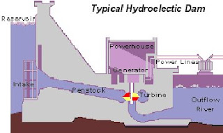
The theory is to build a dam on a large river that has a large drop in elevation. The dam stores lots of water behind it in the reservoir. Near the bottom of the dam wall there is the water intake. Gravity causes it to fall through the penstock inside the dam. At the end of the penstock, there is a turbine propeller, which is turned by the moving water. The shaft from the turbine goes up into the generator, which produces the power. Power lines are connected to the generator that carries electricity to your home and mine. The water continues past the propeller through the tailrace into the river past the dam. By the way, it is not a good idea to be playing in the water right below a dam when water is released!
Parts of a Hydroelectric Plant
Most conventional hydroelectric plants include four major components:
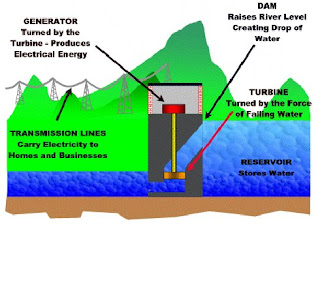
Dam. Raises the water level of the river to create falling water. Also controls the flow of water. The reservoir that is formed is, in effect, stored energy.
Turbine. The force of falling water pushing against the turbine's blades causes the turbine to spin. A water turbine is much like a windmill, except the energy is provided by falling water instead of wind. The turbine converts the kinetic energy of falling water into mechanical energy.
Generator. Connected to the turbine by shafts and possibly gears so when the turbine spins it causes the generator to spin also. Converts the mechanical energy from the turbine into electric energy. Generators in hydropower plants work just like the generators in other types of power plants.
Transmission lines. Conduct electricity from the hydropower plant to homes and business.
Now we are going to share with you HOW HYDROTURBINES WORK!
Water flows from a dam or reservoir through a valve called a penstock that regulates the flow. It then passes through a spiral-shaped pipe to make the water spin. The spinning water makes a turbine turn. The turbine then powers an electrical generator while the water is released downstream.
To make the generator work properly the turbine must spin at a constant speed. Using a speed governor to open and close water gates surrounding the turbine does this. This controls the speed and volume of water flowing to the turbine.
It is also possible to turn off the flow of water altogether using an enormous valve, so that maintenance can occur.
The amount of electricity that can be produced by hydroelectricity generation depends on two things: the rate at which the water flows and the head of water. This is the difference in height between the water in the dam or reservoir and the water below the turbine.
The theory is to build a dam on a large river that has a large drop in elevation. The dam stores lots of water behind it in the reservoir. Near the bottom of the dam wall there is the water intake. Gravity causes it to fall through the penstock inside the dam. At the end of the penstock, there is a turbine propeller, which is turned by the moving water. The shaft from the turbine goes up into the generator, which produces the power. Power lines are connected to the generator that carries electricity to your home and mine. The water continues past the propeller through the tailrace into the river past the dam. By the way, it is not a good idea to be playing in the water right below a dam when water is released!
Parts of a Hydroelectric Plant
Most conventional hydroelectric plants include four major components:
Dam. Raises the water level of the river to create falling water. Also controls the flow of water. The reservoir that is formed is, in effect, stored energy.
Turbine. The force of falling water pushing against the turbine's blades causes the turbine to spin. A water turbine is much like a windmill, except the energy is provided by falling water instead of wind. The turbine converts the kinetic energy of falling water into mechanical energy.
Generator. Connected to the turbine by shafts and possibly gears so when the turbine spins it causes the generator to spin also. Converts the mechanical energy from the turbine into electric energy. Generators in hydropower plants work just like the generators in other types of power plants.
Transmission lines. Conduct electricity from the hydropower plant to homes and business.
 How Much Electricity Can a Hydroelectric Plant Make?
The amount of electricity a hydropower plant produces depends on two factors:
How Far the Water Falls. The farther the water falls, the more power it has. Generally, the distance that the water falls depends on the size of the dam. The higher the dam, the farther the water falls and the more power it has. Scientists would say that the power of falling water is "directly proportional" to the distance it falls. In other words, water falling twice as far has twice as much energy.
Amount of Water Falling. More water falling through the turbine will produce more power. The amount of water available depends on the amount of water flowing down the river. Bigger rivers have more flowing water and can produce more energy. Power is also "directly proportional" to river flow. A river with twice the amount of flowing water as another river can produce twice as much energy. As you should know, the main part of the hydro turbine is the most important part—the generator! But do you know how does the hydro turbine works?
Well, hydraulic turbine converts the energy of flowing water into mechanical energy. A hydroelectric generator converts this mechanical energy into electricity. The operation of a generator is based on the principles discovered by Faraday. He found that when a magnet is moved past a conductor, it causes electricity to flow. In a large generator, electromagnets are made by circulating direct current through loops of wire wound around stacks of magnetic steel laminations. These are called field poles, and are mounted on the perimeter of the rotor. The rotor is attached to the turbine shaft, and rotates at a fixed speed. When the rotor turns, it causes the field poles (the electromagnets) to move past the conductors mounted in the stator. This, in turn, causes electricity to flow and a voltage to develop at the generator output terminals.:D
In the next post, we will be going into the details of the turbines.
Signing off,
Hydroelectricians!:D
Subscribe to:
Posts (Atom)
